My 2-year-old has Type 1 Diabetes. This is a condition that requires constant monitoring, so that insulin can be administered at the right time and in the right doses to ensure he doesn’t die.
When he was first diagnosed, we used fingerpricks and a blood glucose meter to assess Blood Glucose (BG) levels and calculate the insulin dose to be given by injection.
I’d just like to note, that none of the below is used for medical decision-making, it is only an indicator.
A few months after diagnosis, we were provided with an insulin pump, and a Continuous Glucose Monitor (CGM) – the pump allows us to deliver much smaller doses of insulin, and the CGM provides a measurement of glucose levels every 5 minutes – the only fingerpricks we need are for calibration about 4-5 times per day.
The CGM is wireless, and this allows us to read it with a device other than the insulin pump. There’s plenty of documentation online, but there is a device you can build which is known as an xBridge. It reads the Glucose levels wirelessly from the CGM with a wireless microcontroller (specifically a Wixel by Pololu), and pushes that to an Android Phone running a special application via an HM-10 Bluetooth module.
The phone pushes the data up to “The Cloud” – “The Cloud” is a term which normally equates to “Someone else’s computer”, but in this case, it’s mine. The server runs an application called Nightscout, which interfaces with a MongoDB instance to collect the readings.
Nightscout also publishes current levels and some other useful data in a JSON format, which can be used to display on a Pebble smartwatch. My wife has one of these, but I don’t – So I decided to build something else as a “Desktop display” for his BG readings.
The output I need to parse comes in the following format:
{
"status":[{
"now":1519203661659
}],
"bgs":[{
"sgv":"11.8",
"trend":3,
"direction":"FortyFiveUp",
"datetime":1519201987940,
"filtered":225536,
"unfiltered":232480,
"noise":1,
"bgdelta":"0.3",
"battery":"62",
"iob":"0",
"cob":0}],
"cals":[{
"slope":995.2425082371145,
"intercept":20781.66273980129,
"scale":1}]
}
The fields we are interested in are:
• now: This is the current UNIX timestamp (plus milliseconds)
• sgv: The Glucose Level
• datetime: The UNIX timestamp (plus milliseconds) of the last reading
• direction: What direction the Glucose level is moving in (possible values are: Flat, SingleUp, SingleDown, FortyFiveUp, FortyFiveDown, DoubleUp, DoubleDown)
• bgdelta: This is the delta between this reading and the last. I don’t currently use this, but it’s useful for a future enhancement.

The Hardware:
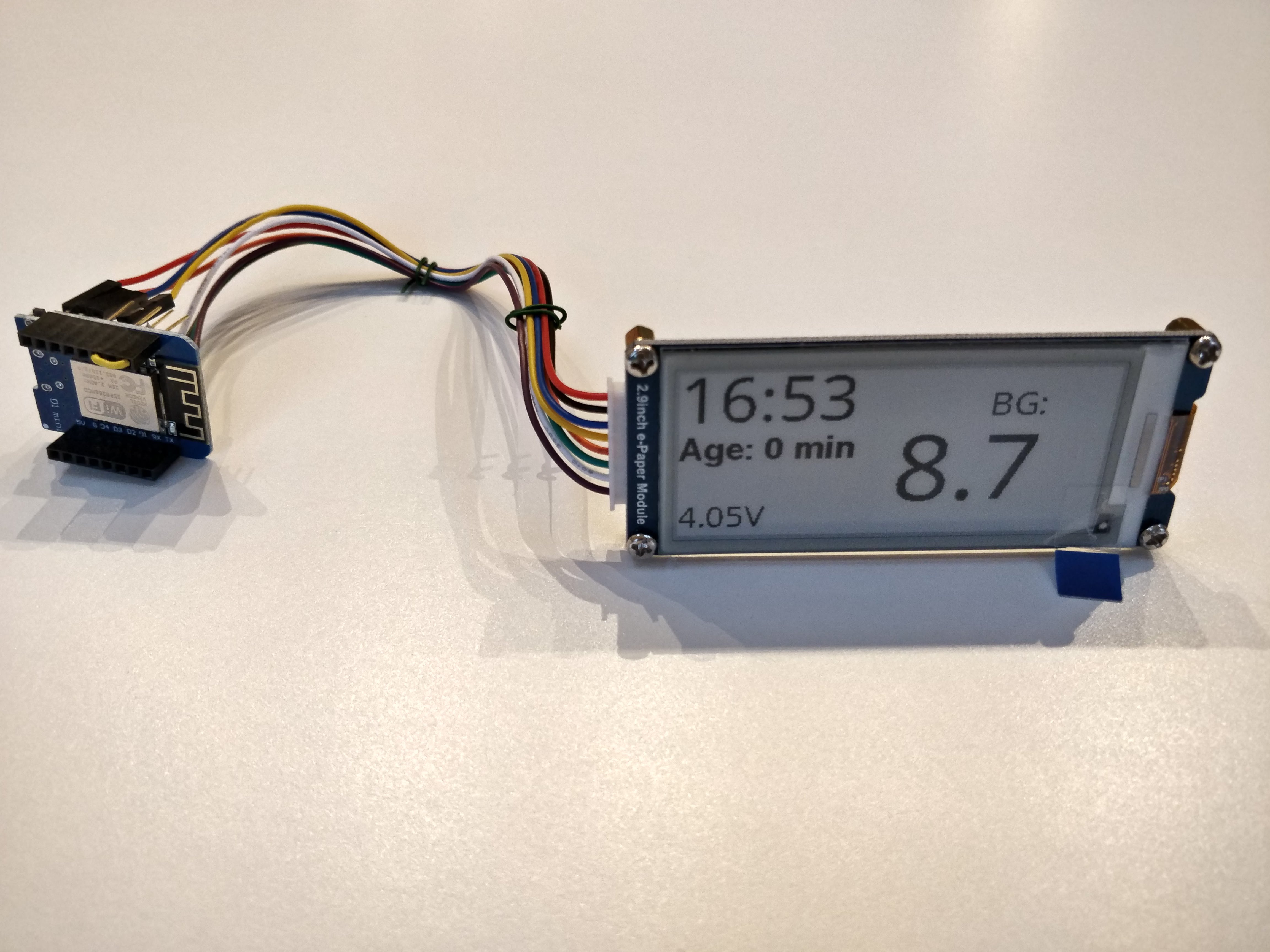
I needed something small, wifi-enabled, easily programmable, and low-power. The ESP8266 is a low-cost Wifi module with a microcontroller onboard, which is compatible with the Arduino development environment, which I was already familiar. I managed to pick up a Wemos D1 mini for about £3. Perfect.
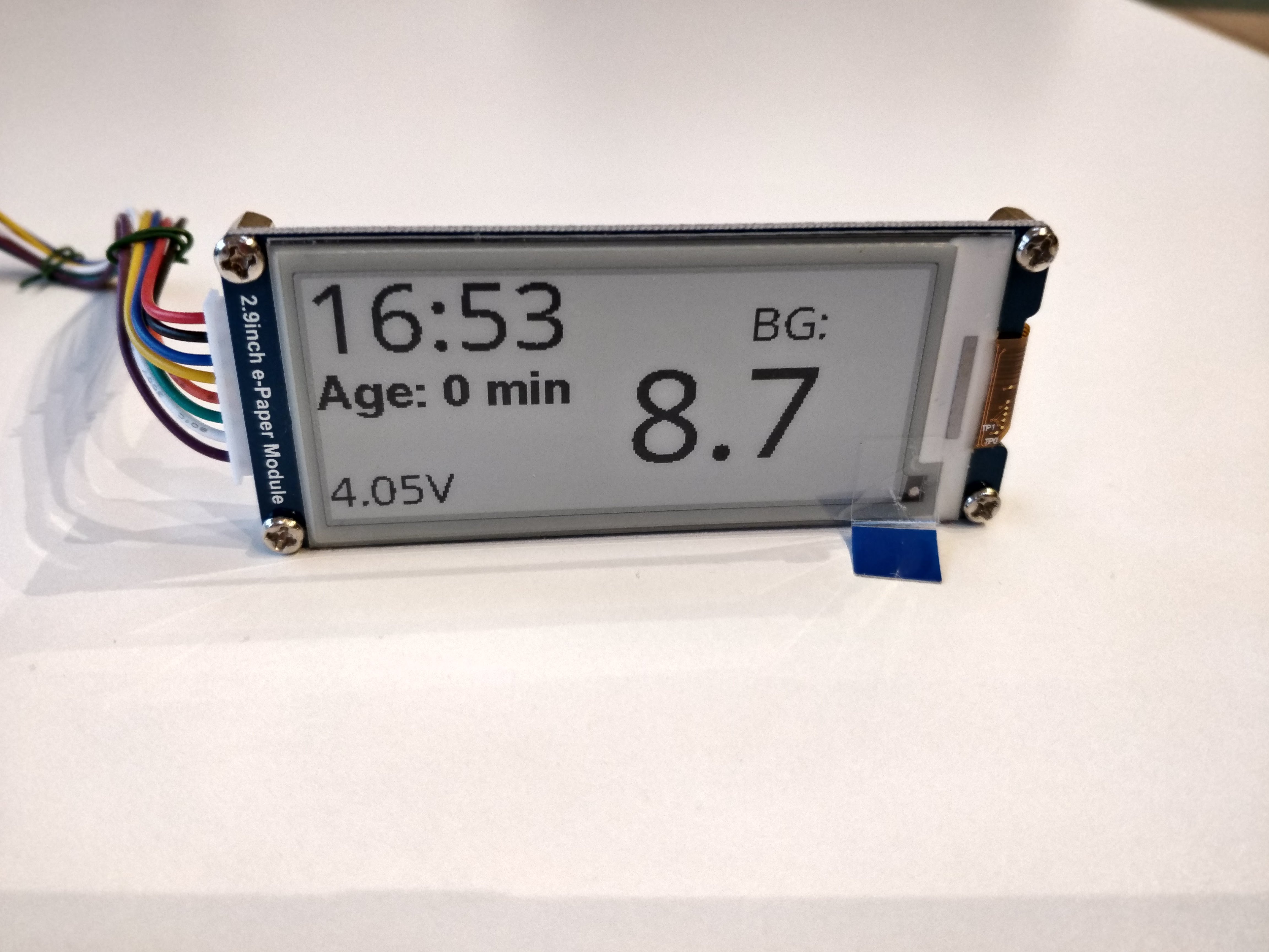
I also needed a display. I initially went for an HD44780 20×4 LCD display with an I2C interface, though power drain was a little high, as it’s difficult to read in sunlight without the backlight, which obviously draws power all the time. Eventually I found a 2.9” e-paper module with an SPI interface. Even better, the logic level for this is 3.3V, the same as the ESP8266 (versus a standard Arduino which outputs 5V logic, needing a level shifter) This was connected as follows:
• BUSY -> D2
• RST -> D4
• DC -> D3
• CS -> D8
• CLK -> D5
• DIN -> D7
• GND -> GND
• 3.3V -> 3.3V
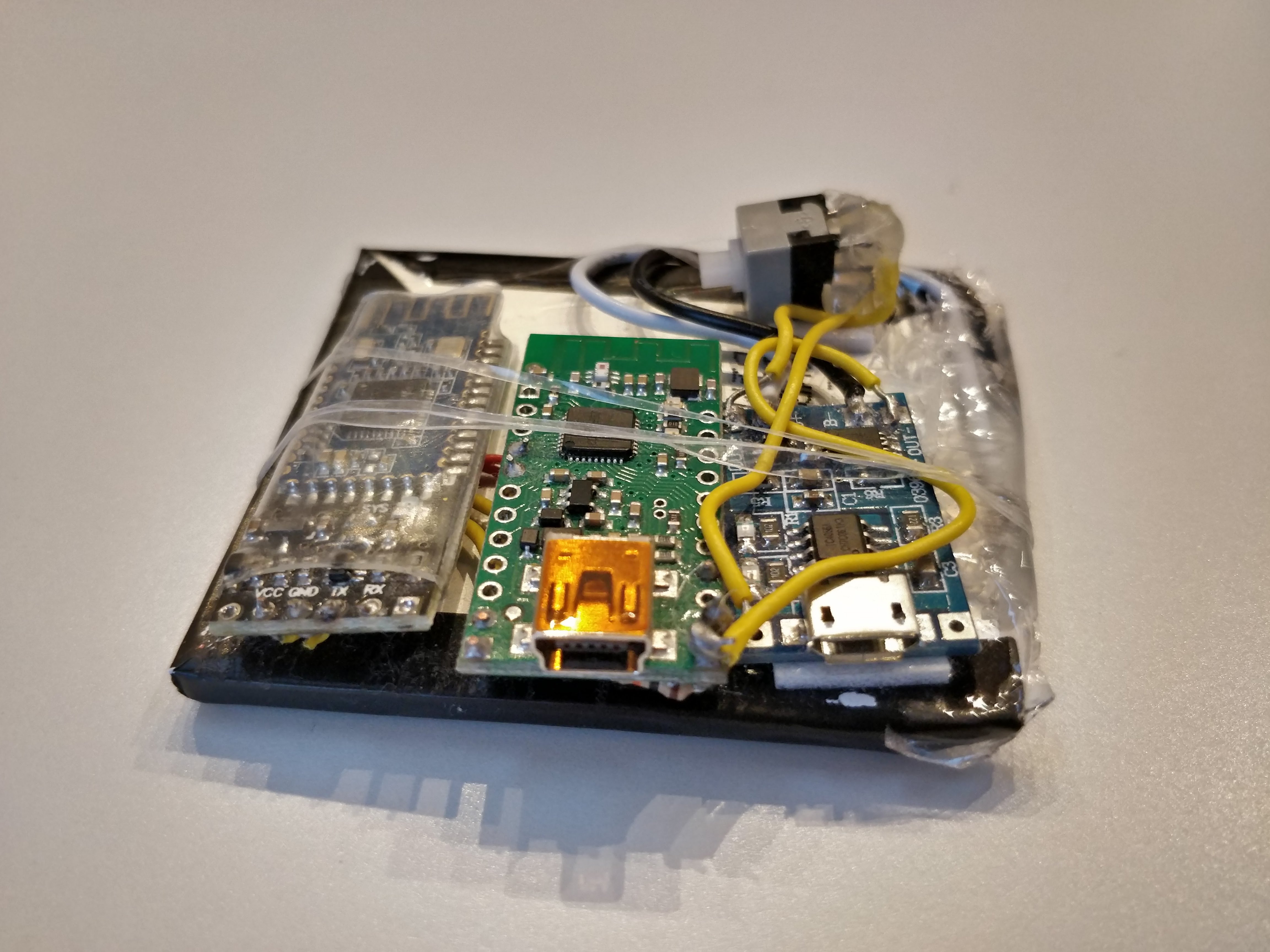
As this can run from 3.3V (and works well down to about 2.7V) – I could use a single Li-Ion 3.7V battery. Li-Ion has a maximum voltage of 4.2V, so I needed to use the “5V” input of the Wemos D1, which pushes the power through its internal 3.3V regulator. Looking at the datasheet of that regulator, it has a dropout voltage of 0.4V, so anything below 3.7V will be unregulated. This is just about within spec, so I grabbed a knock-off Samsung battery from ebay, which already has overcurrent and under-voltage protection, so I could use a Li-Ion charging board without this protection.
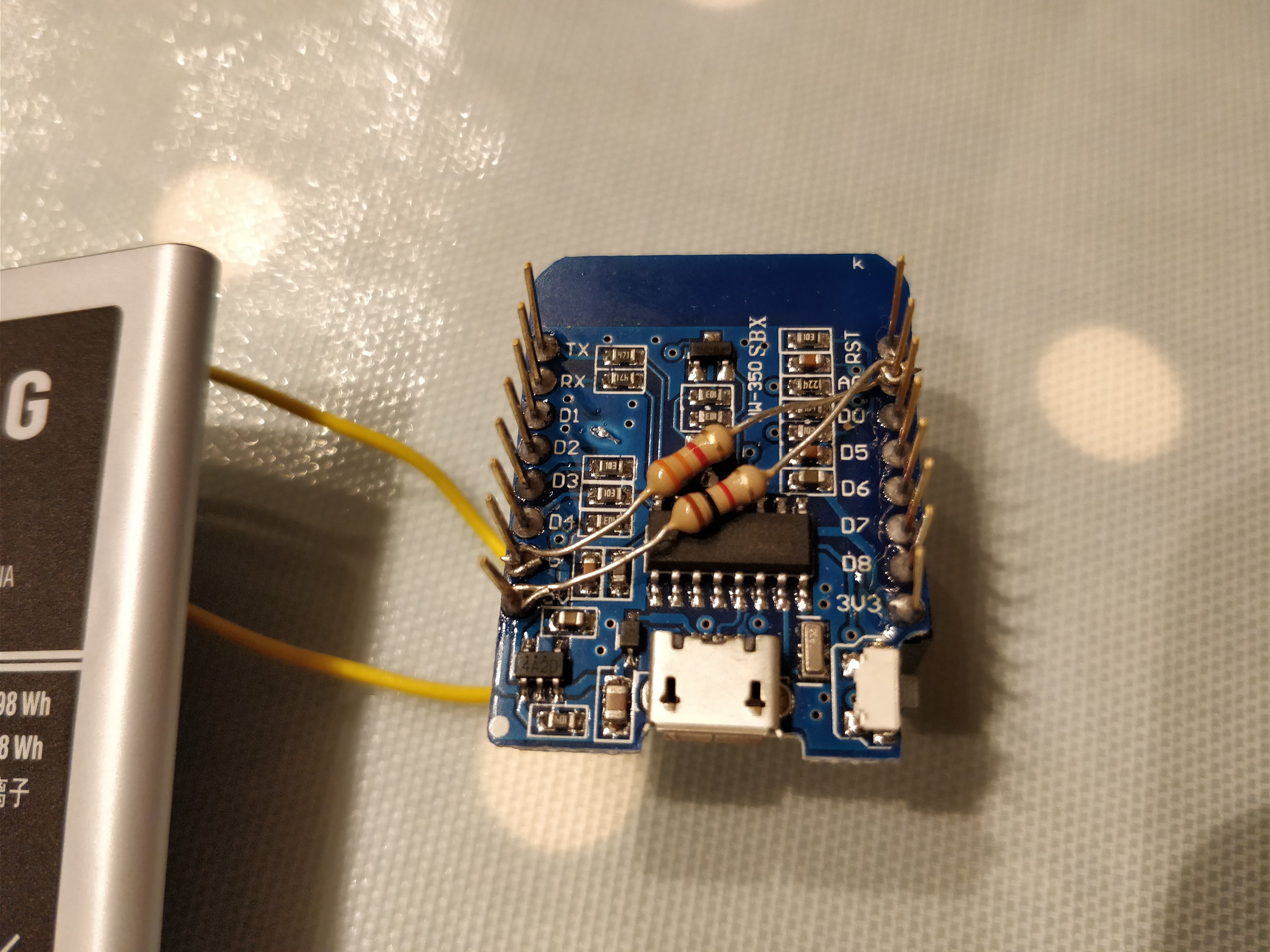
One other modification I made – I wanted to be able to read the voltage of the battery – I couldn’t do this directly from the power, but the Wemos D1 mini is able to read voltages of up to 3.3V on pin A0. Problem is, my battery can run up to 4.2V. I used 2 resistors in a simple voltage divider – 5V -> 100K -> A0 -> 330K -> GND to give a maximum voltage on pin A0 of 3.22V at 4.2V input.
As for the Code, we want the ESP8266 to do a few jobs:
• Connect to Wifi
• Download the JSON
• Parse the JSON
• Get the variables into readable format
• Display them on the screen
• Go to sleep
I can go into more detail later if anyone is interested, but the code is uploaded to https://github.com/robjohnc/nightscout_wemos_epaper, which *should* be fairly well documented.
Awsome! I have been thinking about doing the exact thing for a few weeks and started googling. After reading a lot I by chance found you already have done exactly what I had in mind. I will try/adapt it for our setup so our son can monitor his bg level while immersed in online gaming…
Hi,
i am trying to build this display, but it seems, that there are some lbraries missing or changed in a way that they are not working anymore.
Any hints?
Many thanks 🙂
The biggest change was ArduinoJSON library – I think it upgraded to version 6, where this used 5, and they changed a lot of the functions. Try installing an older version instead, and see if that works.
The same may apply for some of the other libraries, but this was one that definitely broke everything.
Hey, would you be able to pull the data from sugarmate? they have a json file and we don’t need key or anything to access that json file. i would love to get this setup on a wemos d1 mini r2 with a ssh1106 screen
Yeah, I would have thought so! You would need to change the ArduinoJSON parsing section to be able to assign the right values to the right variables, re-jig the display section for the different display, and you might want to change the deep sleep section, as an ssh1106 screen may not retain the image when the microcontroller goes to sleep like an e-paper screen does.
thanks a lot!